
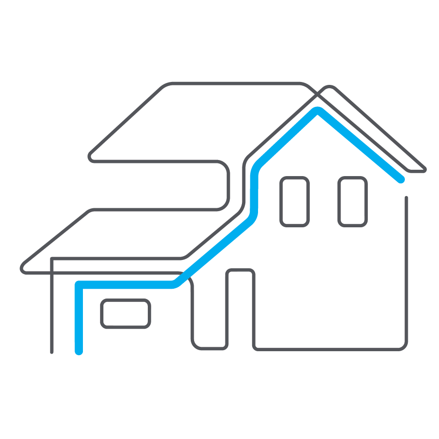
Mounting Cync Dynamic Effects Outdoor Smart Eave Lights
This article provides instructions on mounting and installing your Cync Dynamic Effects Outdoor Smart Eave Lights.
Quickly navigate to a specific section by selecting a link below.
Before You Begin
Create a Layout
Pre-Connect the Lights
Installation
Test & Set Up Lights
Before You Begin
You will need the following items for installation:
- #1 Philips Screwdriver
- Drill with 5/64" and 3/32" drill bits
- Measuring Tape
- Pencil
- Ladder
- Smartphone with the Cync App installed
- (Optional) Wire Cutters
Create a Layout
- Stand in front of your house and identify the following:
- Places you want to illuminate; like eaves, dormers, and rooflines.
- Outlet that powers your lights. Remember to find a Ground Fault Circuit Interrupter (GFCI) electrical outlet within your home’s Wi-Fi range.
- Next, you’ll need to ensure your lights reach the power outlet and ensure you can reach the places you’d like to install the lights.
NOTE: IF YOU DO NOT FEEL COMFORTABLE ON ROOFS OR DO NOT HAVE EQUIPMENT TO SAFELY REACH THE INSTALLATION POINT, MODIFY YOUR LAYOUT TO AVOID THESE AREAS OR HIRE A PROFESSIONAL TO INSTALL YOUR LIGHTS. - Measure the areas of the house you want to install lights. The box includes 106 linear feet of lights (spaced 0.5m apart) and connecting cables. Consider the vertical AND horizontal distance from the outlet. Ensure you are within 106 ft. If you need additional length, you can add more Cync Eave Lights to extend the length up to 150ft using one power supply.
Pre-Connect the Lights
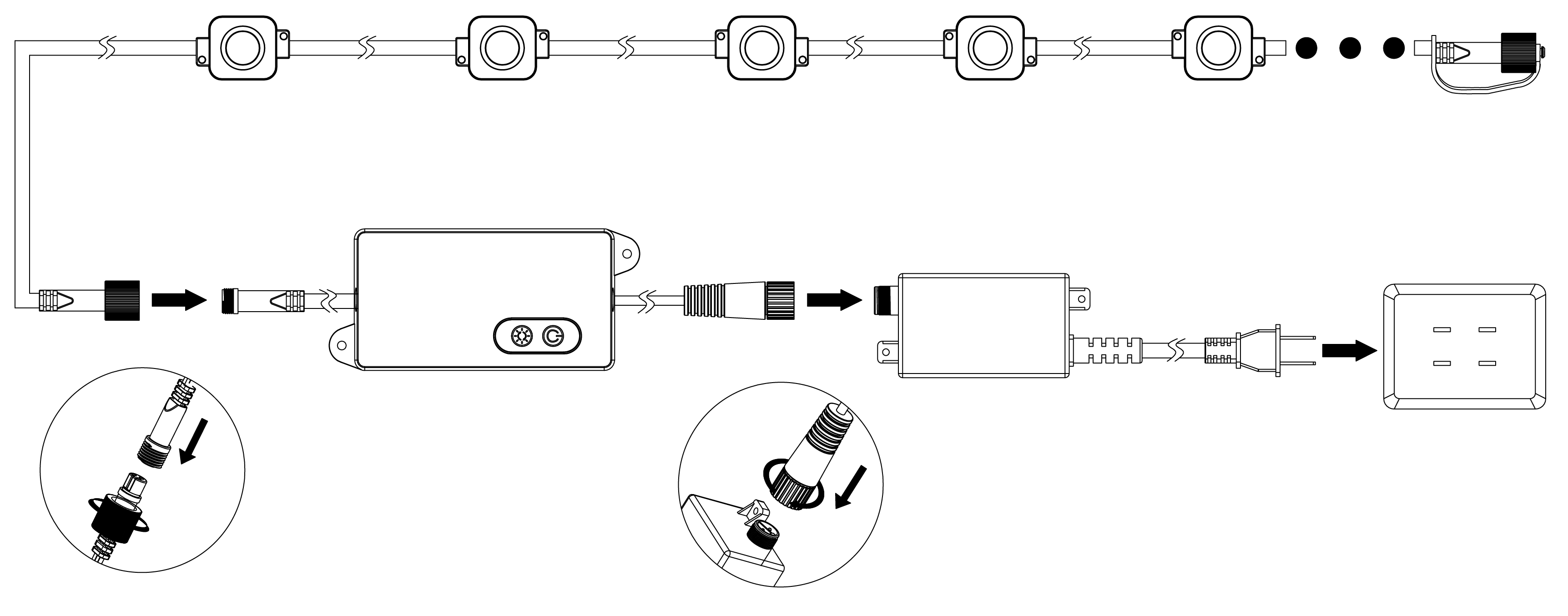
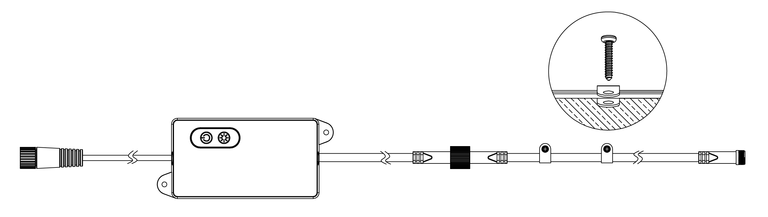
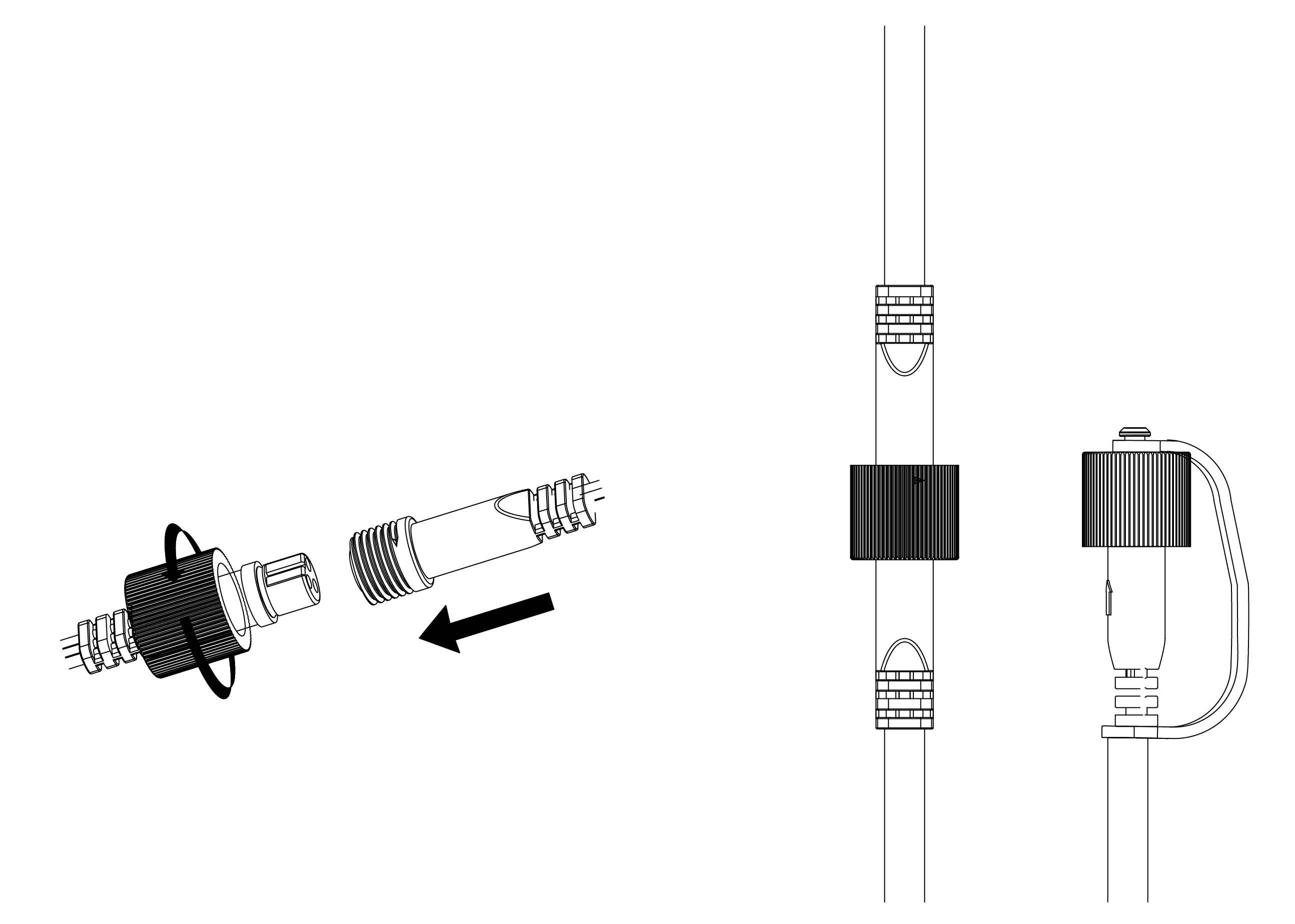
- Connect the lights and extension cables together by inserting the female end into the male end and tightening the screw cap. Connect the light string to the control box and power supply.
- Plug in and turn on to ensure all lights illuminate.
Set Up in the Cync App
- Plug in and power on your lights.
- Refer to the Cync app for set up steps.
Installation
Get Started Installing Your Lights
Before you start mounting and installing your lights, refer to the important notes below.
- When mounting your control box, be sure it is within Wi-Fi range.
- Do not nail through the wires or cables. Instead, use the provided screws and clips.
- Avoid placing the light string over sharp edges as this could damage the wire.
- Plug the power supply into a Ground Fault Circuit Interrupter (GFCI) outlet.
- Ensure control box is installed vertically.
TIP! Use your phone’s Wi-Fi to determine if you will have enough signal strength where you plan on installing your control box.
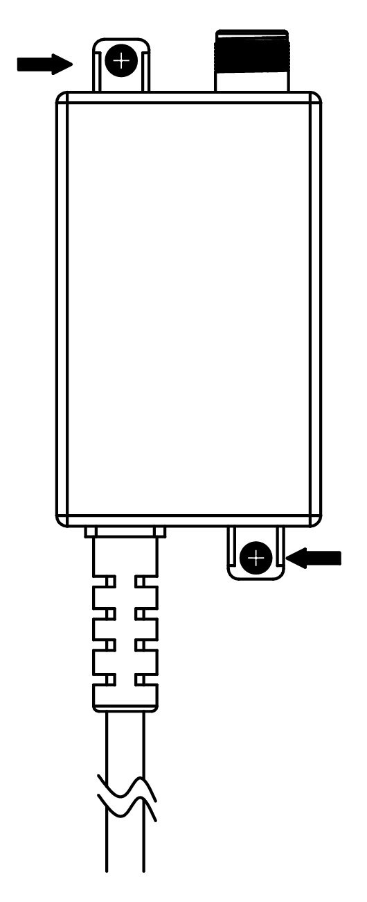
Power Supply Mounting
- Unplug the power supply.
- Mark the hole locations and use an 3/32in bit to drill a pilot hole. Use the 3mm mounting screws and fasten into place.
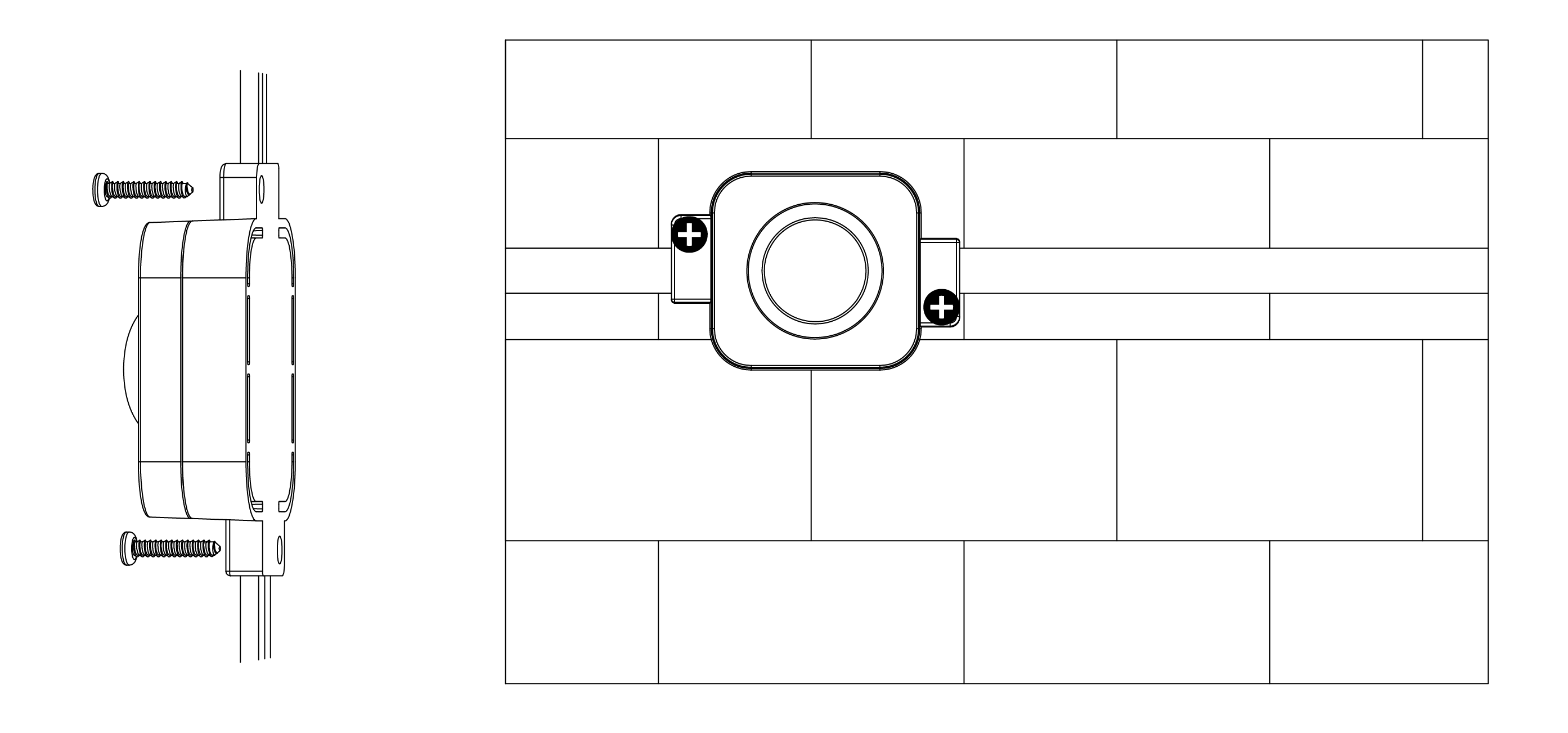
Controller Mounting
- Remove the controller from the bracket. Position the bracket on the wall so the closed end faces downward. Clean the surface with a wipe. Remove the adhesive cover. Press and hold the bracket for 20 seconds to TEMPORARILY hold in place.
- Mark the hole locations and use an 3/32in bit to drill a pilot hole. Use the 3mm mounting screws and fasten into place.
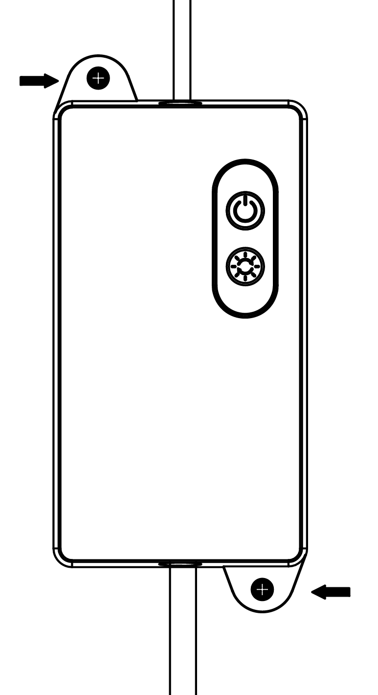
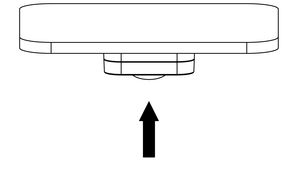
- Slide the controller into the bracket from the top.
Start routing extension cables and lights to fit your layout. Use the cable clips to hold cables in place. For each clip:
- Clean the surface with a wipe. Remove the adhesive cover. Press and hold the bracket for 20 seconds to TEMPORARILY hold in place.
- Mark the hole locations and use an 3/32in bit to drill a pilot hole. Use the 3mm mounting screws and fasten into place.
- Repeat as necessary based on your design.
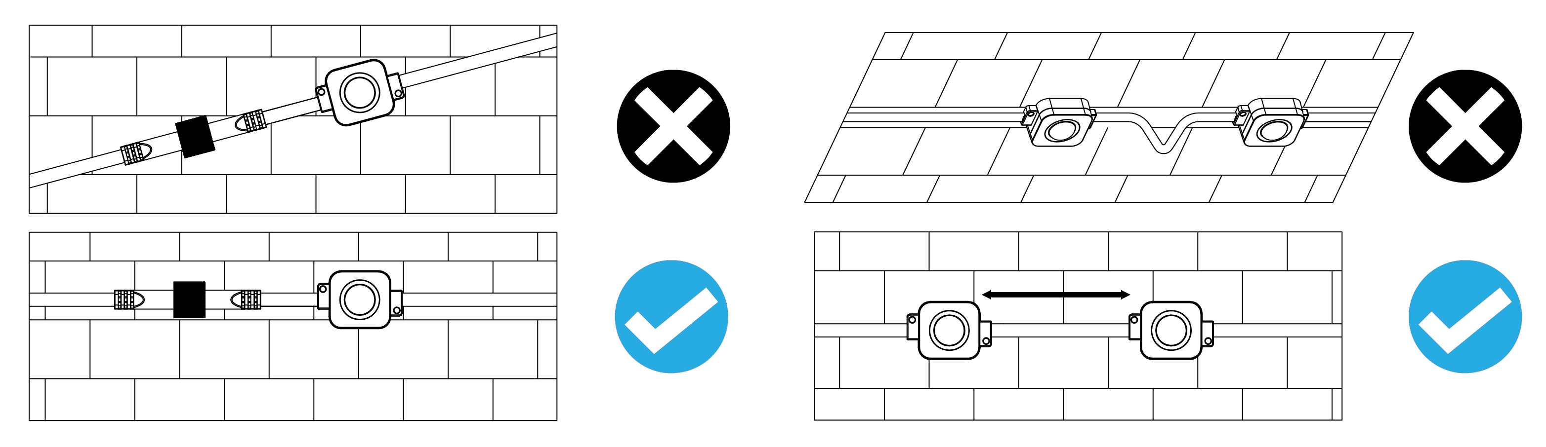
- For a professional look, keep the light strips running parallel to the roofline. Use a tape measure to confirm the lights remain in a straight line, with equal distance from the house or roofline.
- Ensure the light string and connecting cable remain straight to avoid cord damage and disconnection.
- Each light module includes a TEMPORARY adhesive back to hold the light in place to confirm placement. Remove the adhesive back and hold in position for 20 seconds.
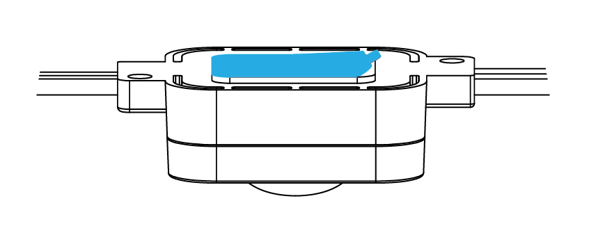
- Once placement is confirmed remove the light module from the bracket.
- Each bracket requires two short mounting screws. Use the hole locations that work best for your installation. Drill a pilot hole with an 5/64in drill bit. Use two 2.5mm mounting screws and fasten into place. If using a drill, use a low-torque setting to prevent stripping or damage.
- Repeat as necessary based on your design.
Trimming (Optional)
- Determine trimming location on the light string. Cut evenly using wire cutters so that no copper wiring is exposed.
- Open the included glue bottle by unscrewing cap and using point on the top of cap to pierce the seal.
- Insert the bottle into the end cap and fill with glue up to the horizontal line on the end cap.
- Slide end cap onto cut end of the light string ensuring no copper wiring is exposed.
Installing the End Cap
- Once the last light string is installed, screw on the end cap to keep out moisture and dirt. Disregard this step if you trimmed and sealed your light string.
Test & Set Up Lights
Plug the power supply into an enclosed weatherproof GFCI-rated outlet. Mount the power supply at a height greater than 12in (0.3m) from the ground surface. Turn on the lights by pressing the power button on the controller or toggling the power button in the app.
Make sure all lights illuminate. If lights do not turn on , or partially light up:
- Confirm the power to the outlet is on.
- Check connections are securely fastened.
- Check to ensure no wires are pinched or pierced.
- Unplug and plug back in.
Change scenes and adjust brightness from the controller. Use the app for enhanced controls, including light shows and music syncing.