Installing Undercabinet Fixtures
Instructions on mounting and installing Undercabinet Fixtures
Quickly navigate to the section you need by following one of the links below.
Before You Begin
Undercabinet Bar Instructions
Direct Wire Installation Method
Plug-In Installation Method
Joining Multiple Fixtures
Undercabinet Puck Instructions
Surface Mount Installation
Surface Mount with Concealed Wiring Installation
Recessed Mount Installation
Direct Wire Installation Method
Before You Begin
BEFORE ATTEMPTING THE INSTALLATION PROCESS, BE SURE TO READ ALL INSTRUCTIONS THOROUGHLY.
- Turn off the power at the main circuit breaker or fuse box.
- Undercabinet Fixtures can be installed directly or plugged in. Read each set of instructions and decide which method is right for you before continuing with installation.
NOTE: One power adapter can power up to 10 Undercabinet Pucks OR 10 Undercabinet Bar Fixtures. For any additional Undercabinet Fixtures needed to be installed you will need to purchase an additional set with a power adapter.
Direct Wire Installation Method
Remove the Knock-Out
- Place a screwdriver into the center, carefully flexing back and forth until removed. Do not leave the removed metal circle inside the fixture.
NOTE: Once the knock-out is removed, the Undercabinet Bar can only be hardwired and can no longer be plugged in.
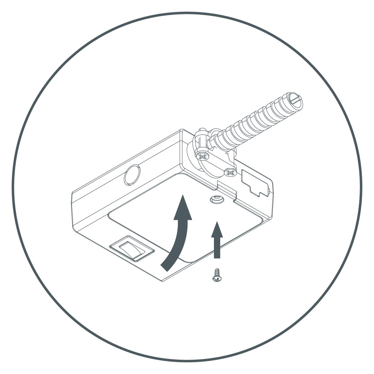
- Loosen the screw and remove connection cover.
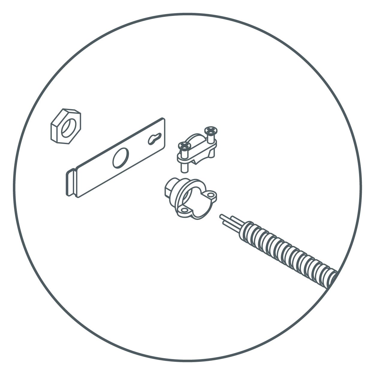
Mount Strain Relief to the Connection Cover
- Securely tighten the nut. Strain relief should be on the outside of the connection cover with the nut on the inside. Push supply cable through the strain relief ensuring that roughly 3 inches of cable is through the fitting. Tighten screws around supply cable.
Connect Wires
- Inside the fixture, there are three wires with a wire connector fitted to each end. Carefully pull these out of the fixture. Do not pull with excessive force.
- Insert each of the three wires from the supply cable into each of the three connectors with their respective color wires. Make sure that all wires are securely gripped, and no bare wires are exposed.
NOTE:- Back plate may need to be removed for direct wire method for easier installation when using a thicker wire gauge.
- Strip supply cable wires with wire strippers to expose 3/8 - 7/16 inches of bare metal for connection.
- Gently push the wires back inside of the fixture. Secure the connection cover back onto the fixture assembly.
WARNING: Do not use power cord when also direct wiring the fixture! Use only one method to power the fixture.

Install Fixture
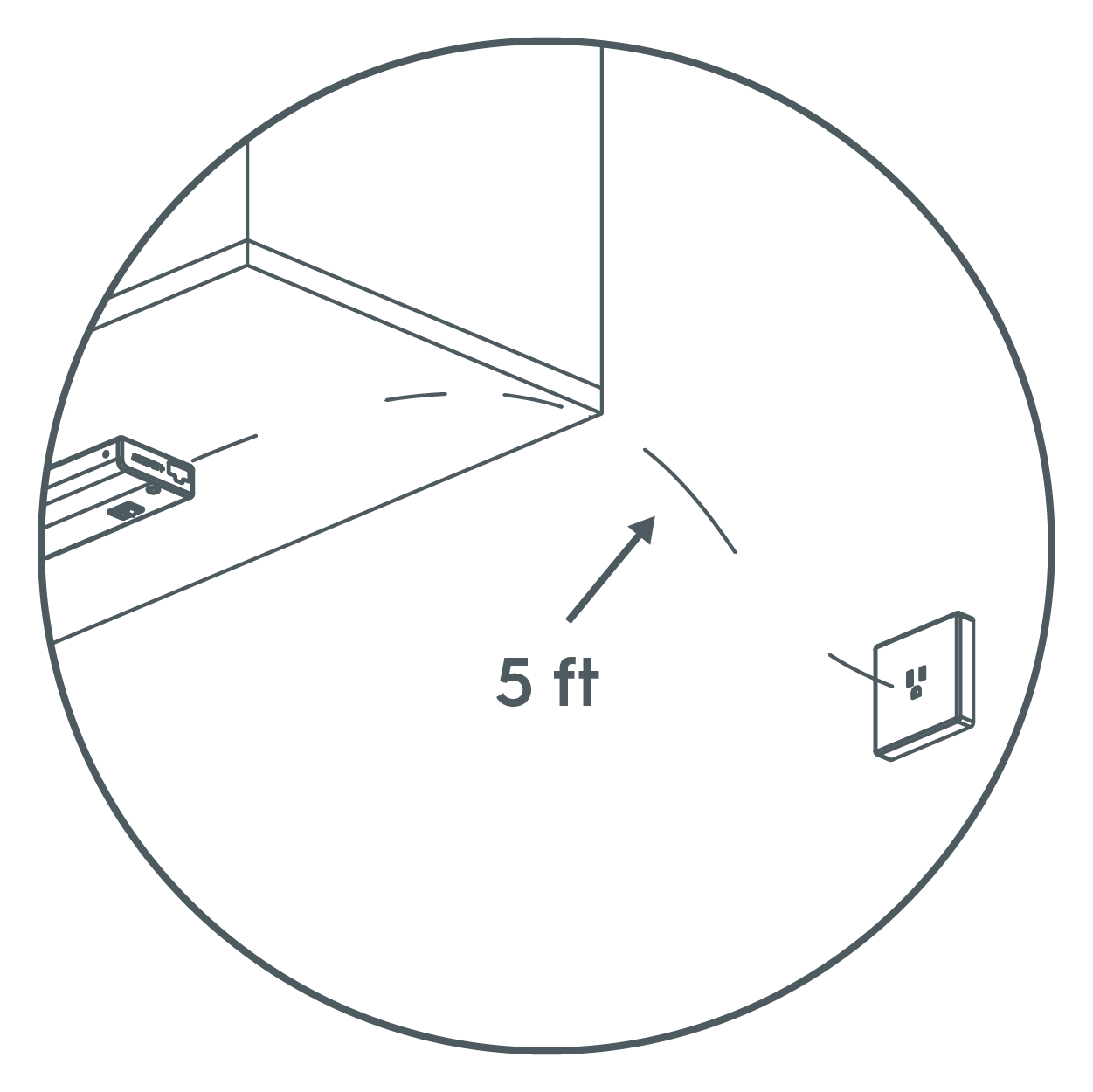
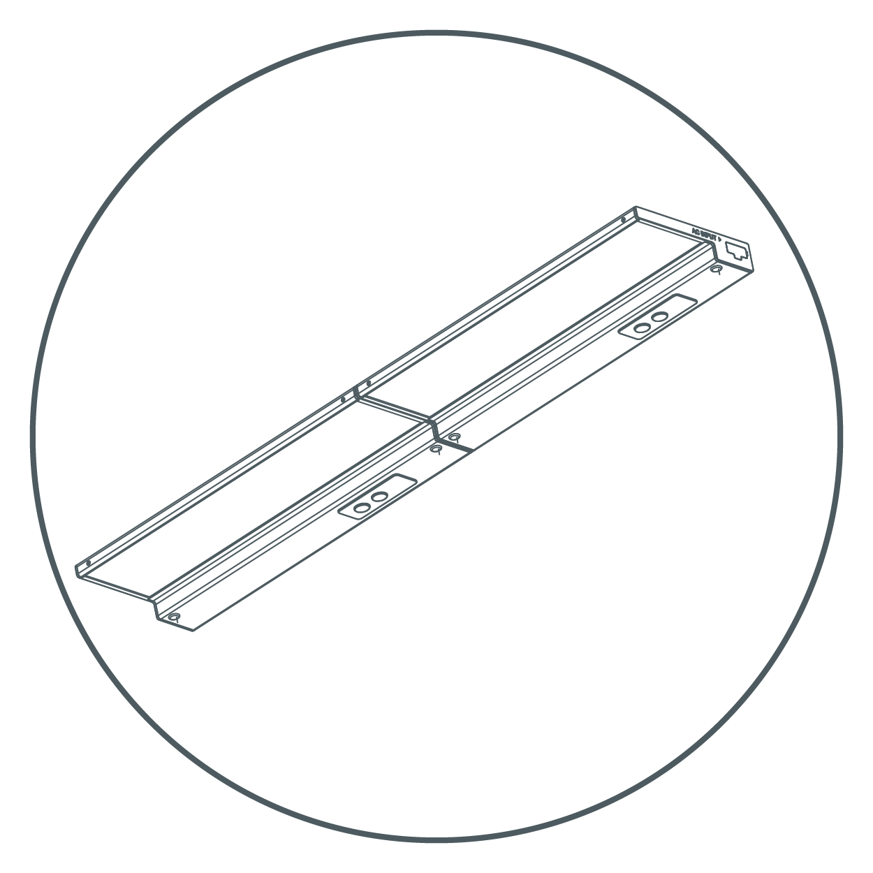
- Place the fixture in the desired position within 5 feet of an outlet. Ensure there is enough space between any cabinet edges and fixtures ends for the cord end. It may be required to pre-drill a pilot hole for screws using a 3mm or 1/8th inch sized drill bit.
- Mount the fixture using a Philips head screwdriver, fully seating the pre-installed mounting screws. Provided screws are suitable for cabinet bottoms 3/8 inch or thicker. It may be required to pre-drill a pilot hole for the screws.
WARNING: If using a drill, set it to a medium speed. Ensure the bit is fully engaged with the screw to avoid stripping. Start slowly until the screw bites into the wood. - Push in the screw hole covers, covering the two exposed screws. When direct wiring and not linking fixtures, make sure to not remove the plastic receptacle cap on each end of the fixture—leave them in place. Turn on the electricity at the circuit breaker or fuse box and verify that the fixture functions properly.
Plug-In Installation Method
Position Fixture
- Locate the position to mount the Undercabinet Fixture. Be sure that it is mounted within 5 feet of an outlet.
- Place the fixture in the desired position. Mount the fixture using a screwdriver, fully seating the pre-installed mounting screws. Provided screws are suitable for cabinet bottoms 3/8 inch or thicker. It may be required to pre-drill a pilot hole for the screws.
WARNING: If using a drill, set it to a medium speed. Ensure the bit is fully engaged with the screw to avoid stripping. Start slowly until the screw bites into the wood.
Connect Fixture to Power Source
- Remove the plastic quick connect cap that covers the INPUT port. Store the cap in a safe place for potential future use. Insert the power cord quick connector into the INPUT port.
- Plug in the power cord to an electrical outlet. Secure cord using cable clips, making sure to keep cord snug to the mounting surface.
- Push in the screw hole covers, covering the two exposed screws. Turn on the electricity at the circuit breaker or the fuse box and verify that the fixture turns ON.
Joining Multiple Fixtures
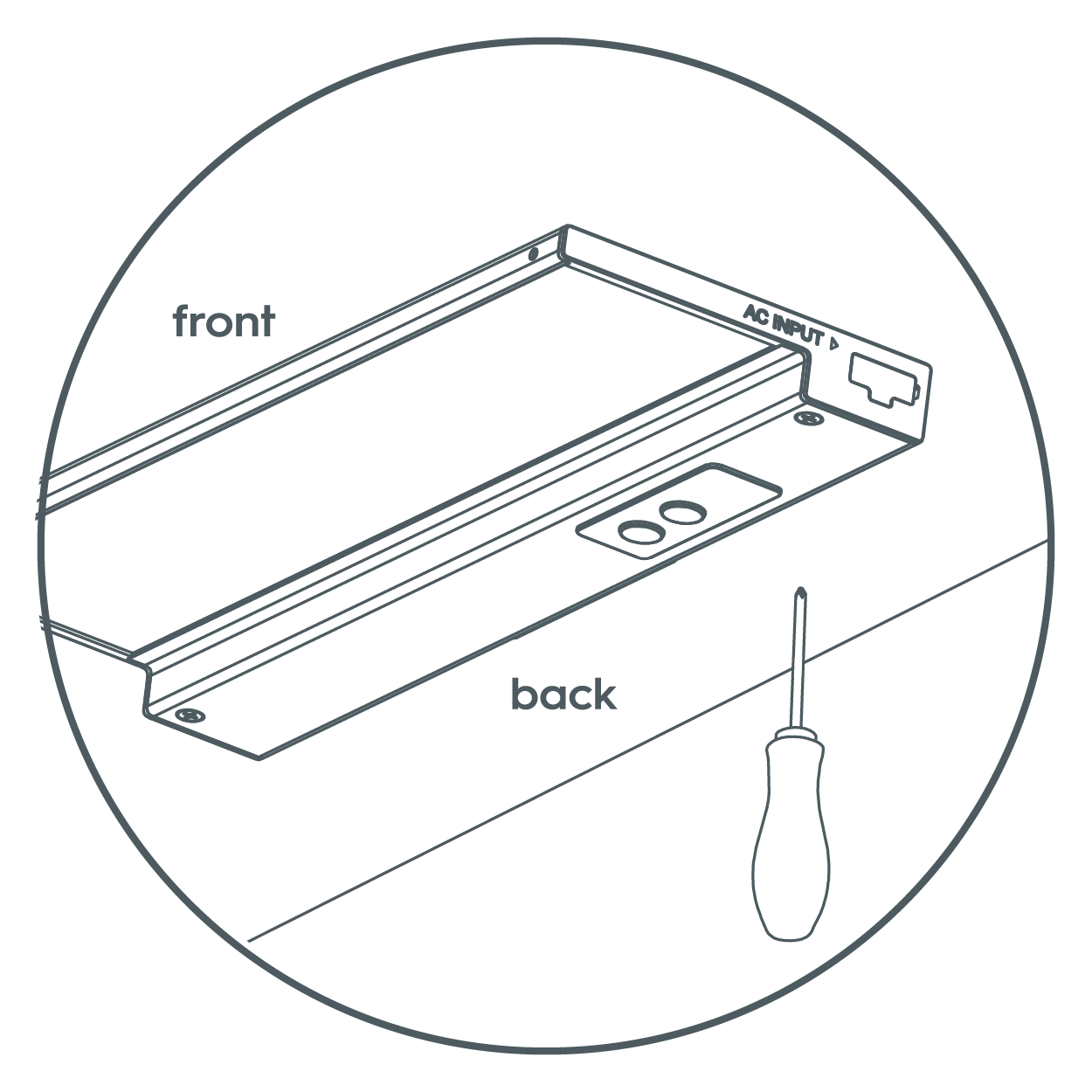
- For multiple fixture installation, make sure all fixtures have been securely mounted and AC Input ports are facing the same direction. (See image below) Fixtures are linkable up to a maximum of 10 units and a wattage maximum of 220W.
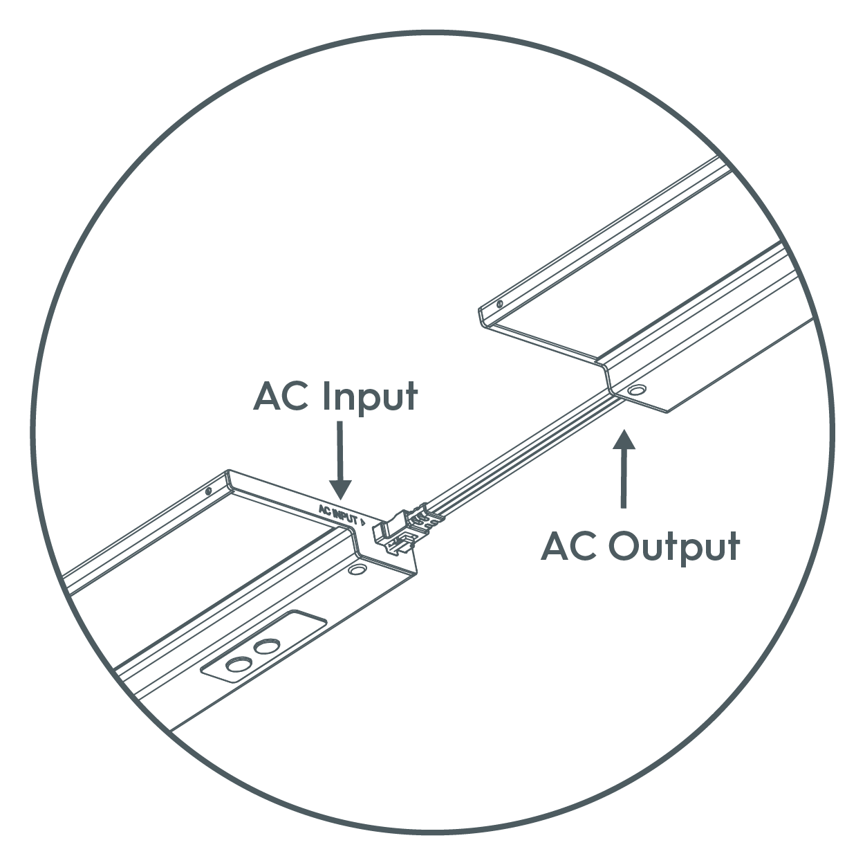
- Remove the plastic quick connect cap that covers the INPUT/OUTPUT port. Store the cap in a safe place for potential future use.
- Using provided jumper cord or recessed connector, link the fixtures together starting with the INPUT/OUTPUT port on the powered fixture and connecting it to the INPUT port on the non-powered fixture. The linking cable and flush connector are designed to only connect one way.
- Ensure plastic quick connect caps are installed in all open parts at the completion of installation.
NOTE: Fixtures can be controlled individually or grouped together in the Cync App whether they are joined together or powered independently.
Traditional Surface Mount Installation
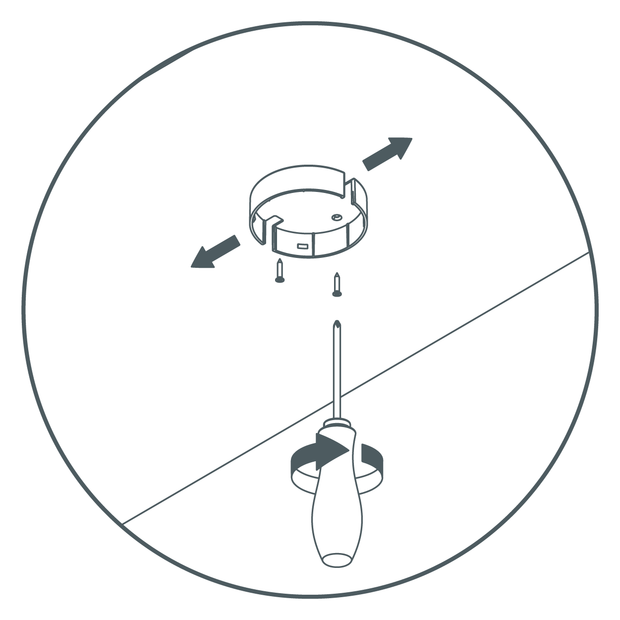
Install Trim Ring
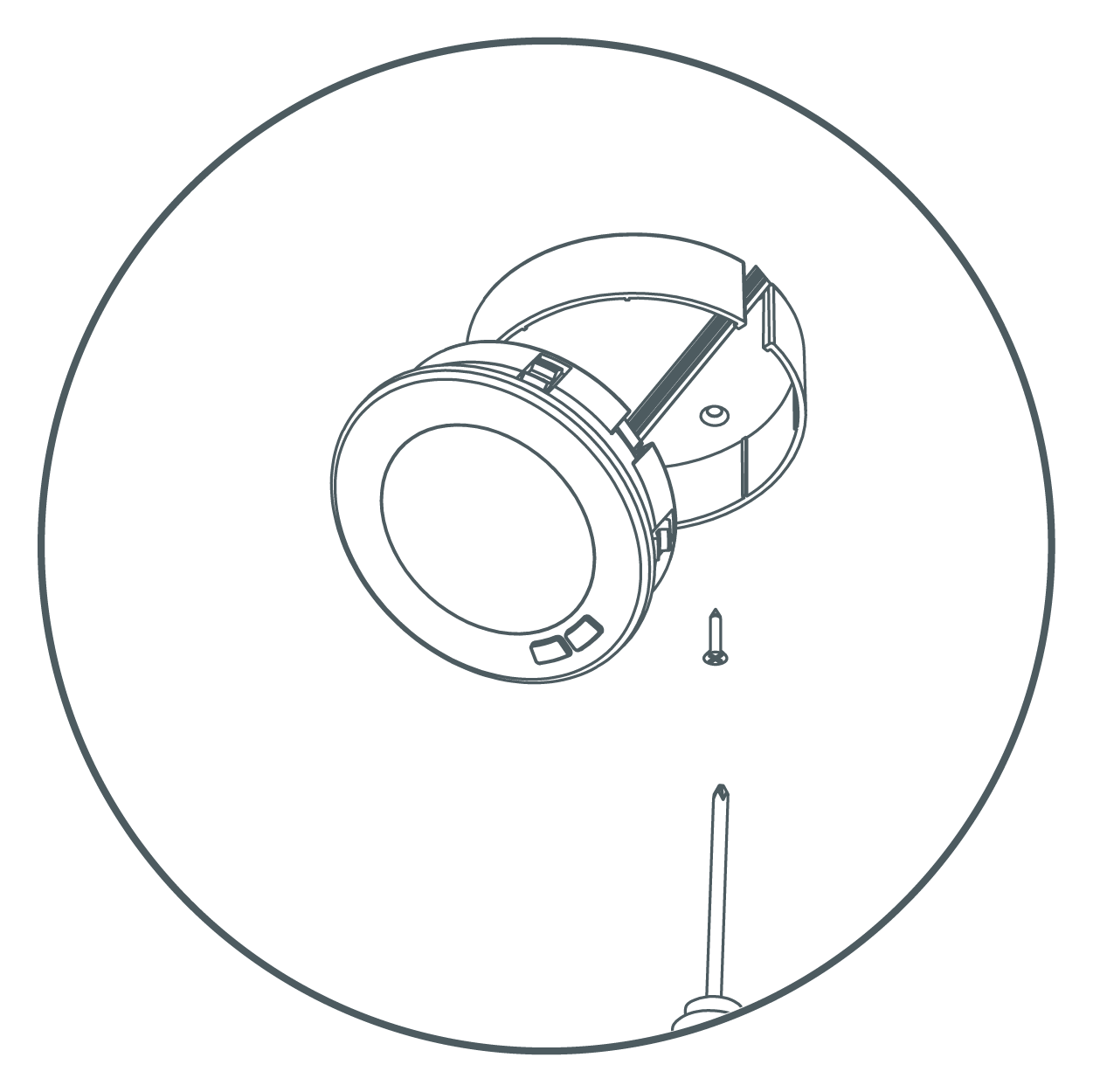
- Separate the trim ring by pushing on the edge of puck assembly.
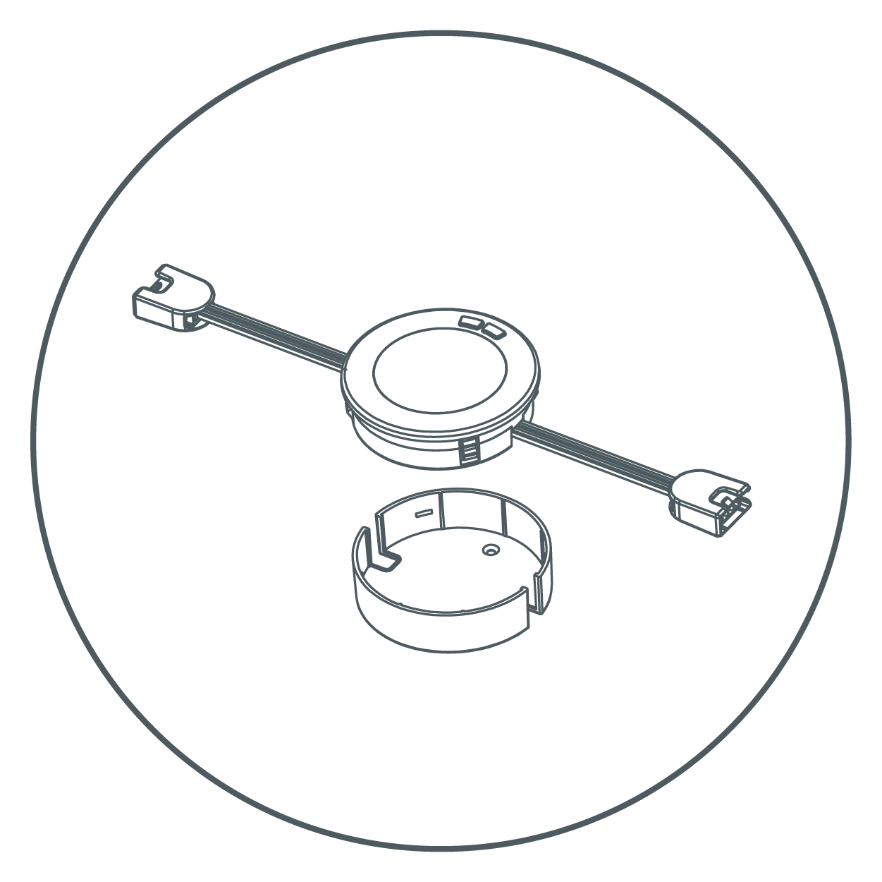
- Place the trim ring in the desired position. Pay attention to cable direction.
- Install the trim ring by inserting the mounting screws. Provided screws are suitable for cabinet bottoms 3/8" or thicker. It may be required to pre-drill a pilot hole for the screws using a 3mm or 1/8" drill bit.
Insert Lamp
- Insert lamp into the trim ring.
NOTE: Pay attention to the cable direction. Make sure that the terminal with "AC IN" mark is in the direction of your socket.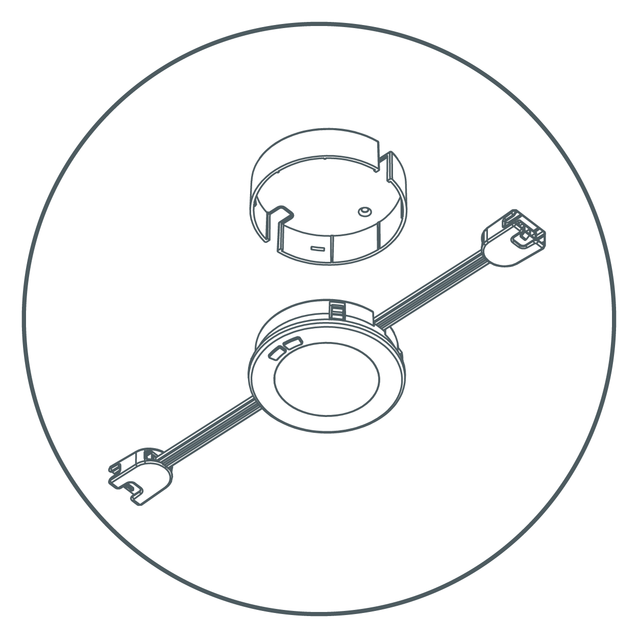
Repeat Steps with Remaining Pucks
- Repeat steps 1 - 4 to install remaining pucks.
NOTE: Pay attention to the distance between pucks. Maximum distance is approximately 19". (Longer linking cables can be purchased separately to increase the distance between pucks.)
Connect Pucks and Plug In
- Connect pucks with each other by using linking cables. (Maximum 10 pucks can be connected per power source.)
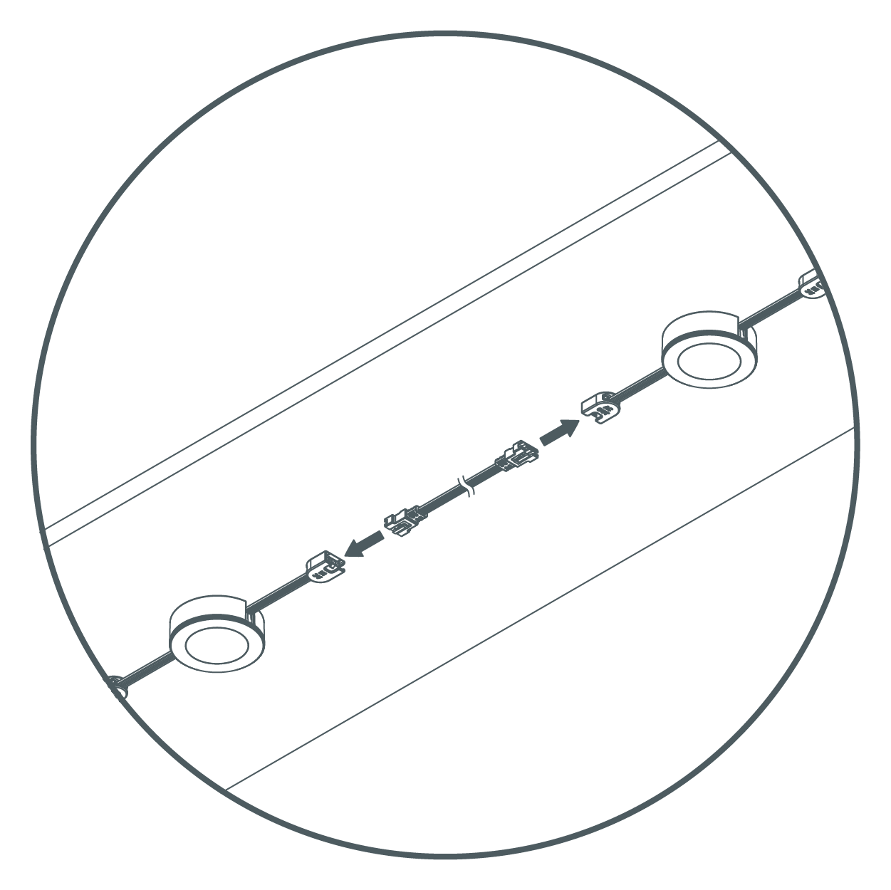
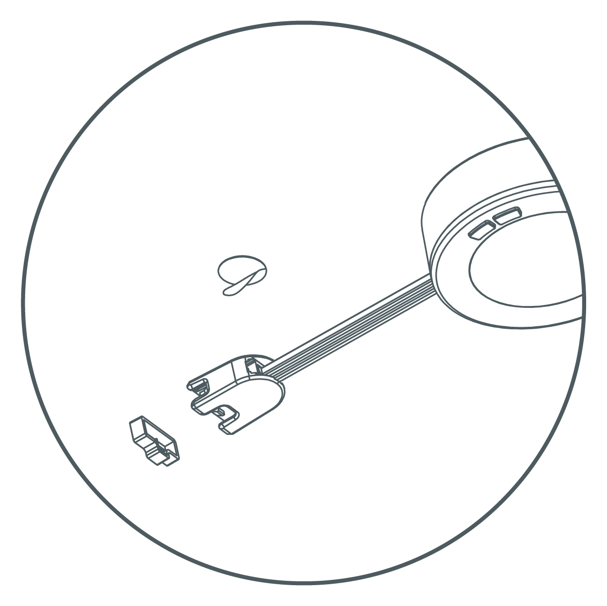
- Cover the last terminal with a terminal cap, then stick it to the mounting surface with provided double-sided tape.
- Plug in the power cord to an electrical outlet.
- Plug in the power to "AC IN" side of the puck, then secure cord using the provided cable clips. Turn on the power at the circuit breaker or fuse box and verify that the fixture functions properly.
Surface Mount with Concealed Wiring Installation
Install Puck
- Separate the trim ring by pushing on edge of puck assembly.
- Use reference the template included to drill two pilot screw holes. Use a hole saw to drill two 1 1/4" cable holes.
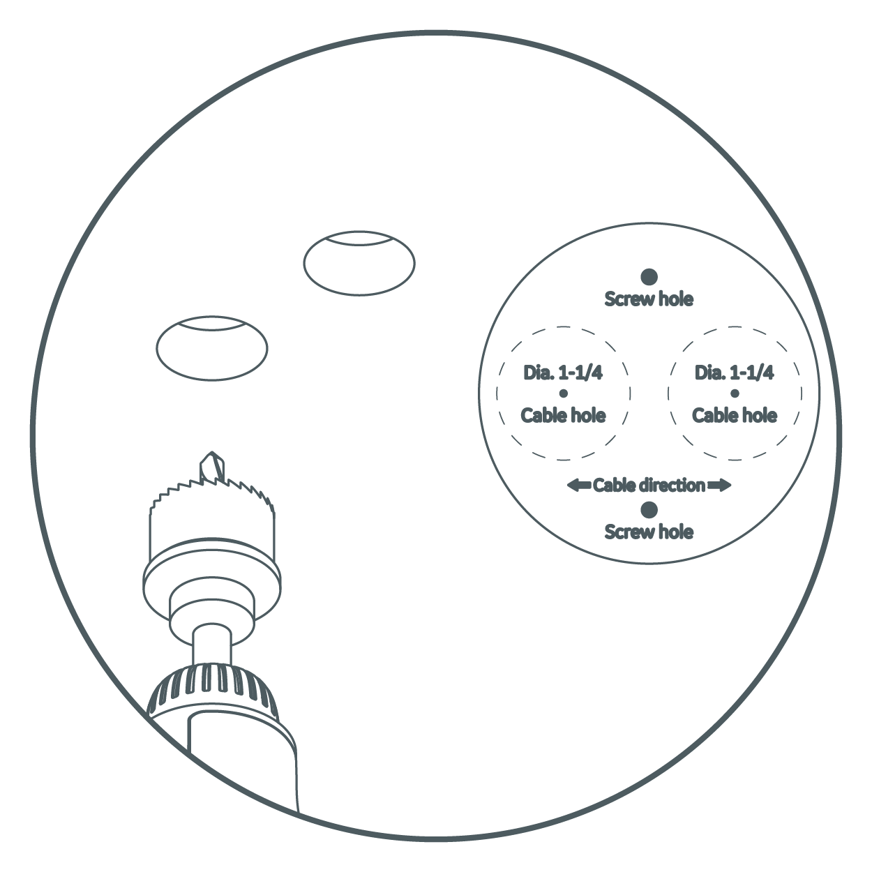
- Pass the cables through the trim ring. Insert terminals through the 1 1/4" holes.
- Tilt the puck slightly, then secure the trim ring to the mounting surface by tightening two mounting screws in the pilot holes.
- Gently push the puck back into the trim ring.
Repeat and Connect to Power
- Repeat steps 1 - 5 to install the remaining pucks.
NOTE: Pay attention to the distance between pucks. Maximum distance is approximately 19". (Longer linking cables can be purchased separately to increase the distance between pucks.)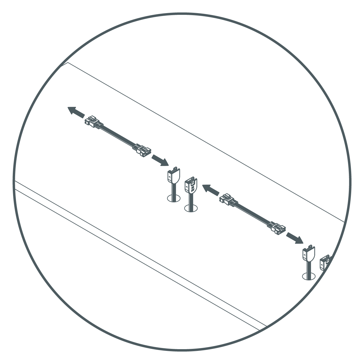
- Connect pucks with each other by using linking cables. (Maximum 10 pucks can be connected per power source.)
- Cover the last terminal with a terminal cap, then stick it to the mounting surface with provided double-sided tape.
- Plug in power cord to an electrical outlet.
- Plug in power cord to "AC IN" side of the puck, then secure cord using the provided cable clips. Turn on the power at the circuit breaker or fuse box and verify that the fixture functions properly.
Recessed Mount Installation
This method of installation is recommended if cabinet bottoms are thinner than 3/4".
Install Puck
- Separate the trim ring by pushing on edge of puck assembly. (INSERT PICTURE FROM traditional surface mount section for illustration.)
- Use a 3" hole saw to drill a hole in the mounting surface.
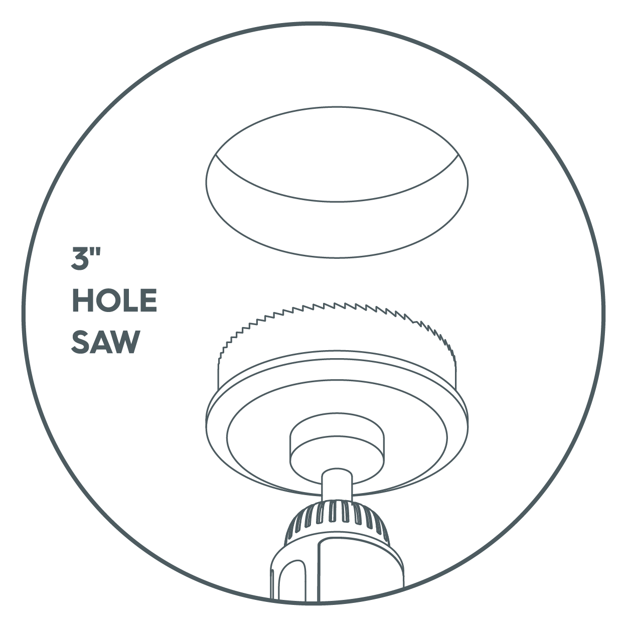
- Pass the cables through the hole and insert the puck into the hole.
NOTE: Pass the cables through the hole and insert the puck into the hole.
Repeat and Connect to Power
- Repeat steps 1 - 3 to install the remaining pucks.
NOTE: Pay attention to the distance between pucks. Maximum distance is approximately 19". (Longer linking cables can be bought separately to increase the distance between pucks). Fixtures are linkable up to a maximum of 10 units and a wattage maximum of 220W.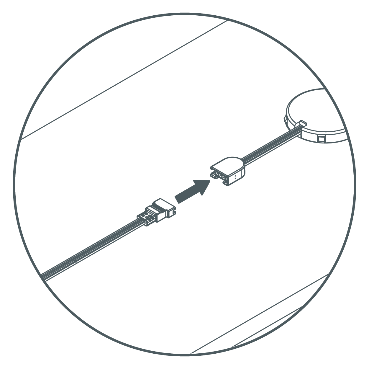
- Connect pucks with each other by using linking cables. (Maximum 10 pucks can be connected per power source.)
- Cover the last terminal with a terminal cap, then stick it to the mounting surface with provided double-sided tape.
- Plug in power cord to an electrical outlet.
- Plug in power cord to "AC IN" side of the puck, then secure cord using the provided cable clips. Turn on the power at the circuit breaker or fuse box and verify that the fixture functions properly.
Direct Wire Installation
The direct wire installation method for the Undercabinet Puck Fixture requires an Undercabinet Fixture Direct Wire Junction Box Accessory (UNCAC-PD-WTLS) to complete these steps. Sold seperately. Read these instructions completelyand carefully before beginning. Alternatively, refer to the instruction manual included with the Undercabinet Fixture Junction Box Accessory.
You will need:
- Undercabinet Fixture Direct Wire Junction Box Accessory (sold seperately)
- Drill
- Screwdriver
- Wire stripper
Installation
- Turn off power source to the power supply where you are installing the junction box.
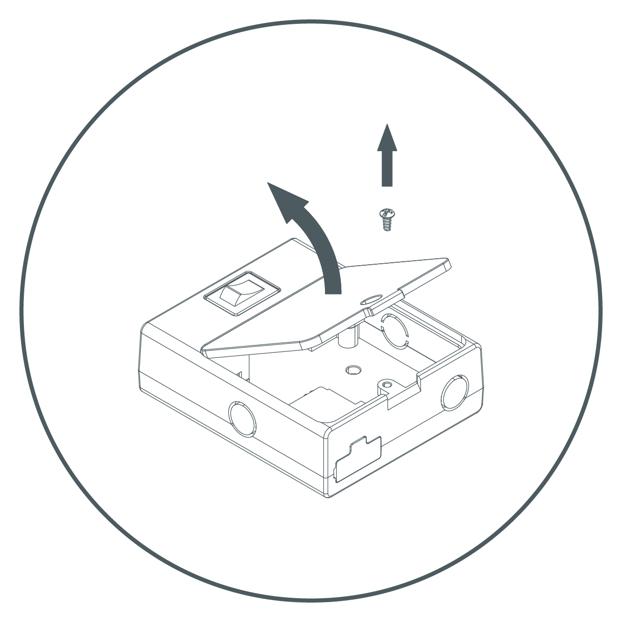
- Remove cover from junction box by unscrewing the screw.
- Choose a suitable knock-out and remove it with a screwdriver.
NOTE: Once the knockout is removed, the box can only be direct wired and can no longer be plugged in.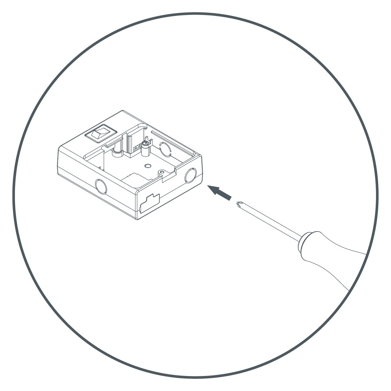
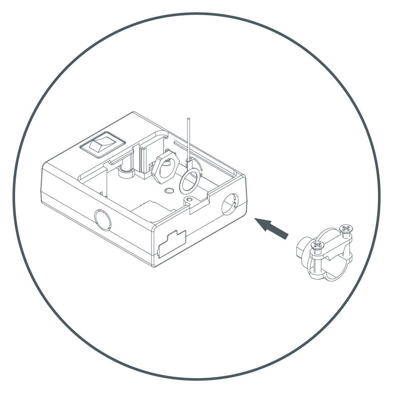
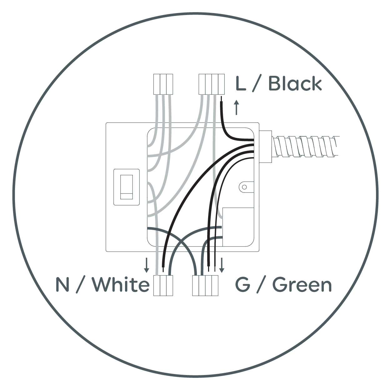
- Mount strain relief to Junction box by inserting the threaded end through the knock-out. Place the eyelet of the copper ground wire around strain relief. Securely tighten nut.
- Push supply cable through the strain relief. Tighten screws around supply cable.
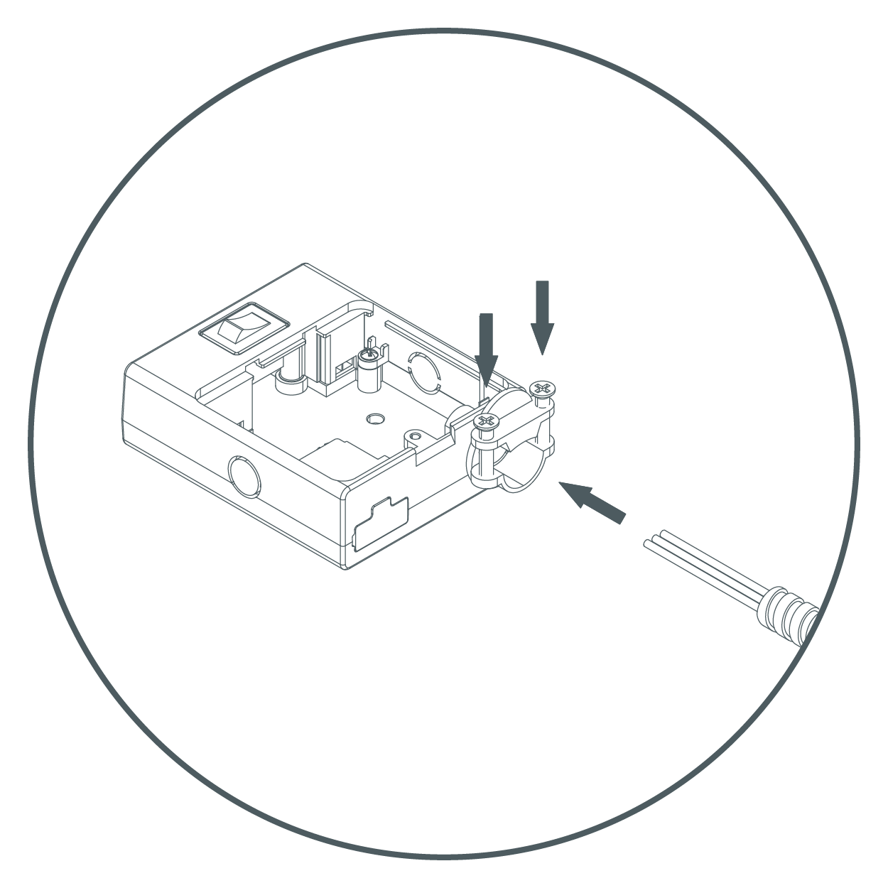
- Inside fixture there are three wire connectors. Insert the three wires from the supply cable into the corresponding wire connectors as shown above. Make sure that all wires are securely gripped, and no bare wires are exposed.
- Arrange the wires inside the box. Fix the box in desired position by securing two installation screws.
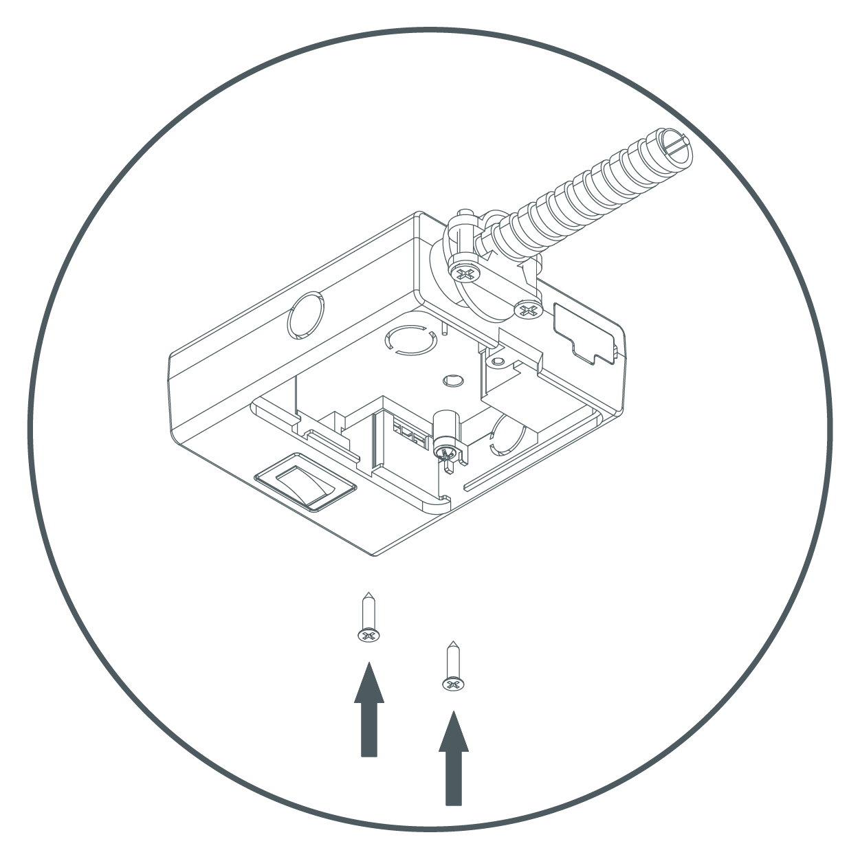
- Put the cover back in place and tighten the screw. Link to the Undercabinet Puck Fixture(s) and turn on power.